As we have looked at earlier, registers are fast data stores located inside the CPU used for intermediate result storage and indicating various states of execution of the system.
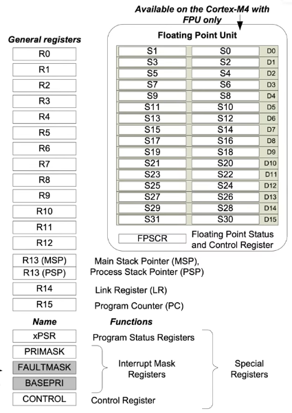
The ARM Cortex-M architecture have much simpler registers than its x86 counterpart. The architecture describes 4 categories of registers based on their purpose in the system. Those are as follows:
1. ARM Core Registers (R0-R15)
The ARM Core Registers are the most commonly used registers by a programmer explicitly. These consist:
13 General Purpose Registers (R0-R12)
Two stack pointer (SP) registers, SP_main and SP_process. These registers contain address of the top of stack. These are banked versions of SP, also described as R13.
The Link Register, (LR), also described as R14. The Link Register stores the return address of a subroutine/function.
The Program Counter, (PC), sometimes described as R15.
SP Registers
The SP registers An Armv7-M processor implements two stacks:
The Main stack, SP_main or MSP.
The Process stack, SP_process or PSP.
The current stack depends on the mode and, in Thread mode, on the value of the CONTROL.SPSEL bit.
A reset selects and initializes SP_main.
2. Special Purpose Program Status Register (xPSR)
The x Program Status Register (PSR) is a 32-bit register that comprises three subsections:
1. Application Program Status Register, APSR
It holds flags that can be written by application-level software, that is, by unprivileged software. APSR handling of application-level writeable flags by the MSR and MRS instructions is consistent across all Armv7 profiles.
Bit
Name
Meaning
31
N (Negative)
Set if the result of an operation is negative (i.e., most significant bit is 1 in signed operations).
30
Z (Zero)
Set if the result is zero.
29
C (Carry/borrow)
Set if there is a carry out (for addition) or borrow (for subtraction). Also used for logical shifts.
28
V (Overflow)
Set if a signed overflow occurs (e.g., result too large for signed int).
27
Q (Saturation)
Set when saturation occurs in certain SIMD/DSP instructions.
26–0
-
Reserved / Unused in APSR
2. Interrupt Program Status Register, IPSR
When the processor is executing an exception handler, holds the exception number of the exception being processed. Otherwise, the IPSR value is zero.
The processor writes to the IPSR on exception entry and exit. Software can use an MRS instruction, to read the IPSR, but the processor ignores writes to the IPSR by an MSR instruction. The IPSR Exception Number field is defined as follows:
In Thread mode, the value is 0.
In Handler mode, holds the exception number of the currently-executing exception.
3. Execution Program Status Register, EPSR
Holds Execution state bits.
T Bit
The M profile supports only the Thumb instruction set, and therefore the processor can execute instructions only if the T bit is set to 1. The T bit is set according to the LSB of the instruction address in the program counter. i.e. To stay in the Thumb instruction set, the LSB of PC Register should always be 1. This is automatically handled by the compiler which adds this 1 bit to the addresses.
Danger
If the T Bit was somehow changed to 0, the processor HardFaults, haulting execution.
ICI/IT Bits
The EPSR (Execution Program Status Register) in ARM Cortex-M cores contains critical execution state information. Two overlapping fields in EPSR — ICI and IT — play key roles in conditional execution and interrupt handling:
IT (If-Then) Bits
Bits: IT (8 bits) spans EPSR bits [26:25] and [15:10].
Purpose: Support Thumb-2 conditional execution using the IT instruction.
Function: Define the condition and execution pattern for up to four instructions following the IT instruction, without requiring branches.
Usage: Common in performance-sensitive code to avoid pipeline flushes caused by branches.
Example:
CMP R0, #0
IT EQ
MOVEQ R1, #1
MOVNE R1, #0
The IT EQ sets the IT bits to conditionally execute the next two instructions based on the result of the comparison.
ICI (Interrupt-Continuable Instruction) Bits
Bits: ICI (2 bits) share the same EPSR bits [26:25] as IT[1:0].
Purpose: Used internally by the processor during interrupt entry to track whether a multi-cycle instruction (like LDM, STM, PUSH, POP) was interrupted mid-way.
Function: Ensures the interrupted instruction can resume correctly upon returning from the interrupt.
These bits are managed by the processor and are not directly visible or modifiable by application code.
3. Special Purpose Mask Registers
In ARM Cortex-M processors, special-purpose mask registers are used primarily for managing exception handling and interrupt masking. These registers are part of the Program Status Registers (PSRs) and control registers that help control execution flow, particularly during interrupt servicing and when implementing critical sections.
These essentially define which interrupts to attend to and which to ignore based on either some priority or fully disable them all.
There are three key special-purpose mask registers in Cortex-M:
1. PRIMASK (Priority Mask Register)
1-bit register that masks (disables) all exceptions except for Non-Maskable Interrupt (NMI) and HardFault.
Useful for disabling all interrupts globally.
Use case:
Disabling interrupts in critical sections to prevent preemption.
Behavior:
PRIMASK = 1: All maskable interrupts are disabled.
PRIMASK = 0: Interrupts are enabled.
__disable_irq(); // sets PRIMASK to 1__enable_irq(); // sets PRIMASK to 0
2. FAULTMASK
Similar to PRIMASK, but it also masks HardFault, meaning only NMI can run.
Mainly used in secure recovery situations like system error handling.
Use case:
When you want to completely block all exceptions, including HardFault, and handle system-level fault recovery.
Behavior:
FAULTMASK = 1: All exceptions except NMI are disabled.
FAULTMASK = 0: Normal interrupt handling.
__set_FAULTMASK(1); // disables all interrupts except NMI__set_FAULTMASK(0); // re-enables them
3. BASEPRI (Base Priority Mask Register)
8-bit register used to define a threshold priority level. Any interrupt with priority numerically higher (i.e., lower priority) than BASEPRI will be masked.
More flexible than PRIMASK — allows selective masking of lower-priority interrupts.
Use case:
Implementing nested interrupts or critical sections with finer control.
Behavior:
BASEPRI = 0: No masking based on priority.
BASEPRI = n: All interrupts with a priority value greater than or equal to n are masked.
__set_BASEPRI(0x20); // masks interrupts with priority ≥ 0x20__set_BASEPRI(0); // unmasks all
4. Special Purpose Control Register
The special-purpose CONTROL register is a 2-bit or 3-bit register defined as follows:
nPRIV, bit[0]
Defines the execution privilege in Thread mode:
0 - Thread mode has privileged access
1 - Thread mode has unprivileged access
In Handler mode, execution is always privileged
SPSEL, bit[1]
Defines the stack to be used:
0 - Use SP_main (MSP) as the current stack.
1 - In Thread mode, use SP_process (PSP) as the current stack. In Handler mode, this value is reserved.
FPCA, bit[2] (With FPU - M4-M7)
Defines whether the FP extension is active in the current context:
 The ARM Cortex-M architecture have much simpler registers than its x86 counterpart. The architecture describes 4 categories of registers based on their purpose in the system. Those are as follows:
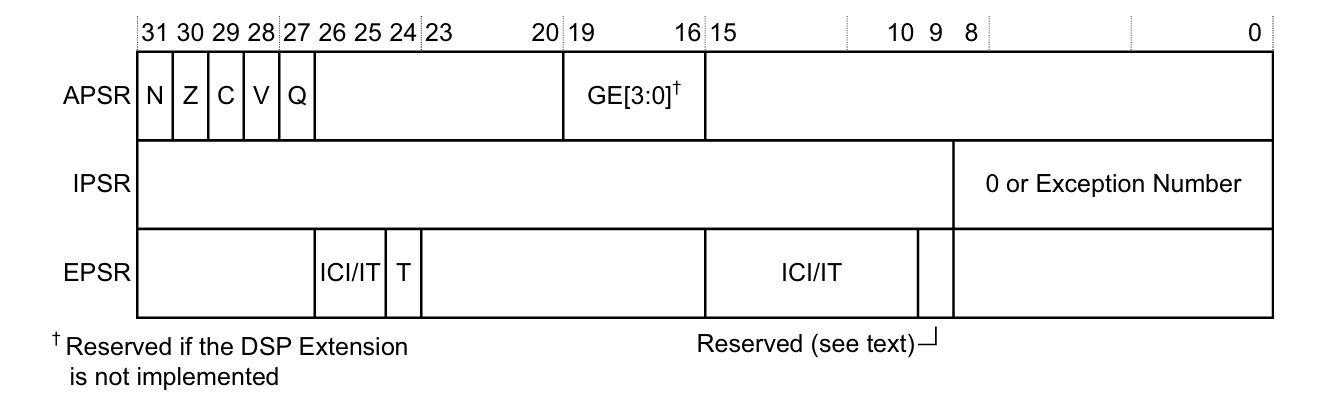 The x Program Status Register (PSR) is a 32-bit register that comprises three subsections:
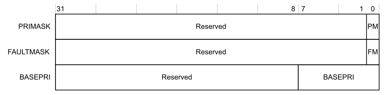 There are three key special-purpose mask registers in Cortex-M: